

The Berrett Hill On30 modules are built to provide both a shelf railroad, and a traveling sectional railroad. Using a 12 inch width, and 4 inch nominal thickness, I am able to move the entire railroad in a 4x4x6 foot trailer, and still maximize the length of run. The design guidelines may be found at:
http://www.berretthill.com/trains/pdfs/berrett_hill_sectional_guideline.pdf
There has been a clamor for details on how the Berrett Hill modules are built. I have been cautious in documenting them because I would not build them all quite the same way again.
In the interest of guiding others away from the more treacherous rocks and stony beaches, here is our story thus far...
Existing Construction
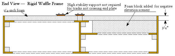
I insist on a foam top on the modules, because in central Maryland there are no flat spots, so every square inch of layout has to slope in one direction or another. A hot wire cutting through foam is so gratifying when creating realistic drainage patterns. Since I prefer deep cuts for dramatic scenic contours, many of the modules are built on a 2 inch base of foam, over a plywood center platform.
In theory the heavy styrene block adds stability to this design, but it flexes more than is desirable both in end-to-end upward bow or sag, and in twist along the module length.
The plywood facia is intended to be the primary vertical beam strength in this design. As shown it has proven to allow too much deformation and movement, particularly when the lower part of the facia flexes in or out from it's vertical alignment.
A more shallow styrofoam top layer is typical of modules that contain switch motors. They are built so there will be enough height inside to protect the connections and machine mounts.
Problem #1 :: Humidity
As it happens, wood parts swell and shrink depending on humidity. Acrylic sheet (Plexiglass) swells even more. Styrene and metal don’t react to humidity at all. Sections built in the dry winter air, and run in the humidity of east coast summers, can have the main line move about in unexpected ways.
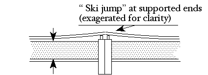
A "ski jump" problem can form at the rigid supports installed at the end plates under the construction guidelines. Note that this issue only rears it's ugly head when building modules with rails-to-the-end design. No such problem will be noticed on a module built with 1" rail setback and floating connector rails -- the minor change in elevation would just be adjusted out of existence at the time of setup...
Anyway, the little ski jump may be great for demonstrating how well 4-4-0s can deal with rough trackage, but without a better design long wheelbase engines with may need to be sidelined during the bad months.
I should note here that a early version of this paper included a statement about humidity affecting styrene and styrofoam. It does not swell in humidity (according to the “Styrene Council” ). I mis-attributed this characteristic from acrylic plastic, which swells quite a bit in high humidity. Take care then, when building in Plexiglass. I hope my error caused no inconvenience.
Thin 1/2" or 3/4" foam creates considerably less movement, but providing close support for the track bed with end grain plywood is the best bet.

A plywood "track beam" under the roadbed will improve the track support, and eliminate foam shrinkage effect. A thin bottom plywood sheet provides a more rigid construction to prevent twisting and stabilize the facia.
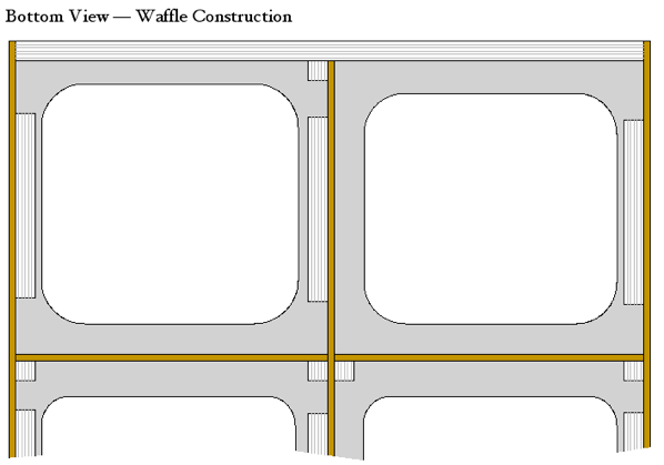
Joe Balint of the North Carolina Sipping and Switching Society has worked out many of the details, and named this "waffle construction".
The underside/cutaway view shows the plywood panel box design. The large holes lighten the structure, and allow access to wiring and fasteners.
Note that the curved corners of the cutouts are important. Curves prevent single point stress fractures; failures that can create "rips" in thin plywood. (This is the same reason airliner windows are always rounded!)
Also note that blocks along the sides of the holes both provide stapling surfaces and support against the stresses of human fingers using the holes as handy carry handles.
Similar "track beam" construction can be applied to modules with a thick foam base.
Spline construction of the beam below the track bed can be bent and formed to follow curves or sinuous trackwork.
Track beams can be notched for bridges and scenery if they are sufficiently tall to start with.
Foam blocks can be fit for any contour, and sliced in place with a hot wire. Facias can be trimmed to the contour before mounting, or cut in place with a jig saw or roto-tool.
Here's a sketch of a typical two foot wide FreMo module built with the same techniques.
Any 2 foot wide module could be built in this fashion.
This is a view of the construction from the underside.
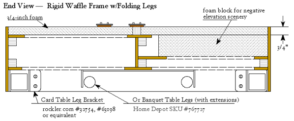
The additional depth of the 6 inch facia could be used to accommodate folding legs, as shown here.
Banquet legs are about 8 pounds, card table legs a bit less. The convenience of folding legs could justify the greater difficulty in handling on all but the largest of modules.
Leg extensions will be required in either case. Simple slip on tubes with pin-through-hole adjustments would be easy to make from plastic plumbing. Some have made clever modifications to card table legs using pegboard holes to simplify construction.
Problem #2 :: Temperature
Metal rails expand and contract in changes of temperature, and when attached to end plates can create significant stress against the module. Sections built in the summer, and chilled in winter storage, will become significantly damaged. Either the frame will bow as shown, or the solder joints will fail, or curves in the track will become dislocated or destroyed as tension tries to pull the track into a straight line. All of these are bad.
The solution for this situation is to install an expansion joint.
This is an unsoldered rail joiner used as an expansion joint. You may have these on an existing module, probably installed by accident.
Though functional, the limitation of such a joint is obvious. When the rail contracts a large gap forms in the running surface of the rail. Should the rail expand the rail ends will butt and unplanned events may occur.
This is a half lap joint. Technically elegant it can be created with a file in about five minutes. Sliding a rail joiner over the joint will hold it together for an almost invisible installation.
As with any unsoldered joint, be sure to run a power feed to every piece of rail for dependable operation.
I'll keep you posted on ease or difficulty on installing this as a retro-fit. I expect to be trying this a number of times...
A discussion with Bob Wynne came up with this approach, for folks more comfortable with a Fast Tracks jig. Similar to the half lap, rail ends are filed to points and installed in the same manner.
Later discussion about this technique indicated that it was too easily “stretched thin”, though it may perform well with a long enough taper. The consensus was that this method might be more trouble than it’s worth.
I’ll try to keep this page up to date as info accumulates...
Kevin Hunter